


Working With PT100:
Platinum
resistance thermometers (PRTs) offer excellent accuracy over a wide
temperature range (from -200 to +850 °C). Standard Sensors are are
available from many manufacturers with various accuracy specifications
and numerous packaging options to suit most applications. Unlike
thermocouples, it is not necessary to use special cables to connect to
the sensor.
The principle of operation is to measure the resistance of a platinum element. The most common type (PT100) has a resistance
of 100 ohms at 0 °C and 138.4 ohms at 100 °C. There are also PT1000
sensors that have a resistance of 1000 ohms at 0 °C.
The relationship between temperature and
resistance is approximately linear over a small temperature range: for
example, if you assume that it is linear over the 0 to 100 °C range, the
error at 50 °C is 0.4 °C. For precision measurement, it is necessary to
linearise the resistance to give an accurate temperature. The most
recent definition of the relationship between resistance and temperature
is International Temperature Standard 90 (ITS-90).
pt100 sensor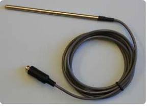
pt100 sensor
This linearisation is done automatically, in software, when using Pico signal conditioners. The linearisation equation is:
Rt = R0 * (1 + A* t + B*t2 + C*(t-100)* t3)
Where:
Rt is the resistance at temperature t, R0 is the resistance at 0 °C, and
A= 3.9083 E-3
B = -5.775 E-7
C = -4.183 E -12 (below 0 °C), or
C = 0 (above 0 °C)
A= 3.9083 E-3
B = -5.775 E-7
C = -4.183 E -12 (below 0 °C), or
C = 0 (above 0 °C)
For a PT100 sensor, a 1 °C temperature
change will cause a 0.384 ohm change in resistance, so even a small
error in measurement of the resistance (for example, the resistance of
the wires leading to the sensor) can cause a large error in the
measurement of the temperature. For precision work, sensors have four
wires- two to carry the sense current, and two to measure the voltage
across the sensor element. It is also possible to obtain three-wire
sensors, although these operate on the (not necessarily valid)
assumption that the resistance of each of the three wires is the same.
The current through the sensor will cause
some heating: for example, a sense current of 1 mA through a 100 ohm
resistor will generate 100 µW of heat. If the sensor element is unable
to dissipate this heat, it will report an artificially high temperature.
This effect can be reduced by either using a large sensor element, or
by making sure that it is in good thermal contact with its environment.
Using a 1 mA sense current will give a
signal of only 100 mV. Because the change in resistance for a degree
celsius is very small, even a small error in the measurement of the
voltage across the sensor will produce a large error in the temperature
measurement. For example, a 100 µV voltage measurement error will give a
0.4 °C error in the temperature reading. Similarly, a 1 µA error in the
sense current will give 0.4 °C temperature error.
Because of the low signal levels, it is
important to keep any cables away from electric cables, motors,
switchgear and other devices that may emit electrical noise. Using
screened cable, with the screen grounded at one end, may help to reduce
interference. When using long cables, it is necessary to check that the
measuring equipment is capable of handling the resistance of the cables.
Most equipment can cope with up to 100 ohms per core.
The type of probe and cable should be chosen
carefully to suit the application. The main issues are the temperature
range and exposure to fluids (corrosive or conductive) or metals.
Clearly, normal solder junctions on cables should not be used at
temperatures above about 170 °C.
Sensor manufacturers offer a wide range of
sensors that comply with BS1904 class B (DIN 43760): these sensors offer
an accuracy of ±0.3 °C at 0 °C. For increased accuracy, BS1904 class A
(±0.15 °C) or tenth–DIN sensors (±0.03 °C). Companies like Isotech can
provide standards with 0.001 °C accuracy. Please note that these
accuracy specifications relate to the SENSOR ONLY: it is necessary to
add on any error in the measuring system as well.
Now come to the point. When you really need to use PT100, then you may think that you will use something like this:
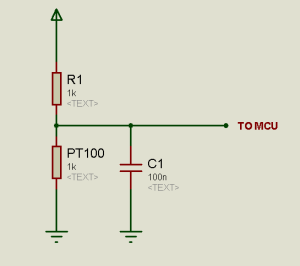
And you will measure the voltage with the
MCU. But if you really planning this, you’ll be disappointed. Because in
this case you may need MCU with 32bit ADC. And such MCU is not
available in most of the local market(it was not at available in my
local market). Also there will be a very little change in the voltage
with the temperature changes. So it will be definitely critical to
measure the temperature in this method.
So what to do now?
You’ve many ways open still now. You can use Bridges(such as Wheatstone Bridge)
or you can use Op-Amp to do this job for you. Basically Wheatstone
Bridge will be a complex one to do the job but will ensure good
performance. But if you don’t need to much accuracy and you don’t want
to be such complex, you can use Op-Amp.
What I did in my case? In my case, I didn’t need so much accuracy. So I used Op-Amp. And did a back calculation.
Ha ha ha! I made a amplifier with a gain of
4.7. And then set the sensor in a known standard heater. Now the time of
back calculation.
I set the heater at
50′C—-> measured the output voltage at the Op-Amp output terminal.
55′C—-> measured the output voltage at the Op-Amp output terminal.
60′C—-> measured the output voltage at the Op-Amp output terminal.
.
.
.
.
200′C—-> measured the output voltage at the Op-Amp output terminal.
205′C—-> measured the output voltage at the Op-Amp output terminal.
And so on…
now, took the data in a table. Now you can imagine what I’m planning to do…
Yes! I coded a look-up table. and from that, I found the temperature data with 5′C steps.
Its done! without any complexity. But if you really need higher accuracy, You must have to use the Bridges.
Yes! I coded a look-up table. and from that, I found the temperature data with 5′C steps.
Its done! without any complexity. But if you really need higher accuracy, You must have to use the Bridges.
IR remote controlled auto/manual room temperature based Fan speed controller.
The main job of this project was to control a fan speed depending on the room temperature in Auto mode and as user defined in Manual Mode.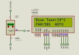
In the Auto mode, the micro-controller (PIC16F73) take the data from the temperature sensor LM35. The LM35 is a precession temperature sensor that have a output of 10mV/’C. So what I did actually here, I kept the ADC_ref. Voltage at 2.5V. So it will count 2.5/255 = 9.8mV/Cnt. Which is almost same as the LM35 provides per ‘C. In Auto mode the fan speed will vary with the temperature changes. When temperature rises, fan speed increases. Temperature falls, speed reduces.
But in Manual mode, user have a choice of His/Her own. A remote (SONY) is provided, the Power button will select the Mode (Auto/Manual) and if Manual Mode is selected, button 1 to 9 will change the fan speed and 0 will stop the fan. A Buzzer is used to inform the user that a button has pressed.
Here is the complete circuit:
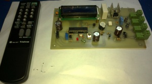
For More Details CLICK HERE


No comments:
Post a Comment
Note: only a member of this blog may post a comment.