Popular Posts

E-bike on 100% green, solar energy(Electric Bikes) Becoming popular!!

Running an E-bike on 100% green, solar energy

One eZeebike owner from Bellville has managed to run his eZee (and house lights) from a solar installation. See his technical account below:

Can it be done?                      Absolutely! Now in 2013. In South Africa.
Is it the right thing to do?     Absolutely! Actually, what is really right to do is to ride your e-bike EVERY DAY.
Is it cost effective?                 Nope, unfortunately not yet. E-bikes are super efficient, and despite all the wars around electricity pricing, this commodity is still phenomenally cheap! E-bikes use very little of what is cheap.
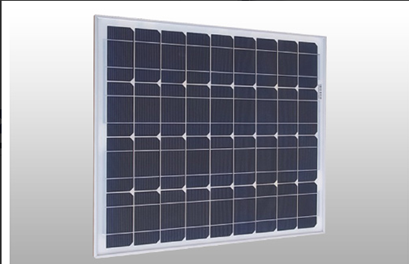
What is required?    1. Solar modules (panels) of 100 – 150 watt, about 1 sq metre.

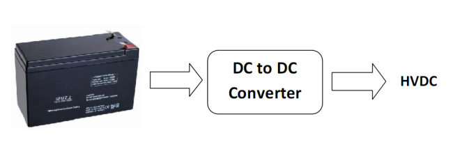
2. A storage battery 12 volt 100 Ah or more. Lead acid (or LA).
We all know what they look like… dangerous, black, messy… put them in a ventilated room away from where you live ! You get sealed ones though. Still dangerous.
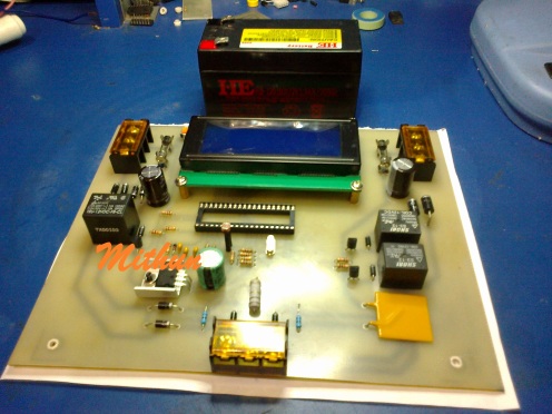
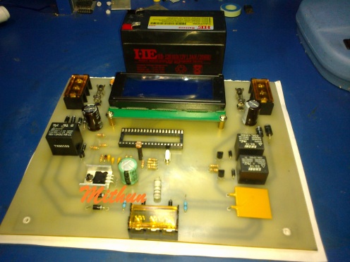
            3. Solar energy regulator (to prevent overcharging)

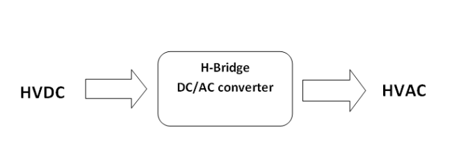
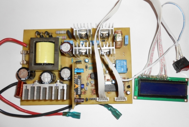
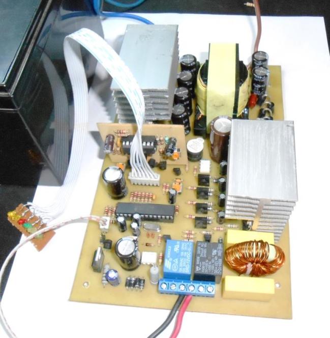
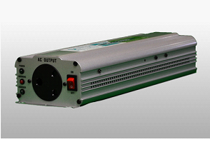
4. Inverter (to make 230 V AC to drive the Li-ion bike charger.)

Sizing is important depending on your situation, there are these factors to consider:
  1. If you live in the Western Cape’s winter rainfall area, you may not be able to charge the bike on 8 x 8 cloudy days, where-as in the rest of the country you can count on enough sunshine most days of the year. (Fully) rainy days in the Cape (Bellville) up to 1 September this 2013 winter were exceptionally many at 10, so even here one can ride on solar energy. In winter!
  2. If you insist to do real time charging, you could get away with a much smaller LA battery, say 50 Ah. Real time means when the sun is actually shining when you connect the Lion charger, and you are ensuring the sun keeps shining (no earthbound human has achieved that ever!) mostly till end of charge (of the bike) which can be up to 5 hours. You can drive only a 2 A Lion charger from 150 watt panels, not the 4 A quick charge ones.
Bottom line 1 – So it comes to the same expense to rather invest in more storage battery capacity and maybe less than 150 watt panels. A big LA storage also helps to ride through passing clouds (which cut down the panels’ output considerably), which must be a rational way of thinking.
  1. If you insist to charge your bike when the sun is not shining, typical of a working person who is away from home during the day and not inclined to trust things to run unsupervised, you want at least 150 Ah in the lead acid department. These very old technology batteries are notorious for giving much less back than was put into them. The bike’s battery is only 400 watt-hours or Wh (40 volt x 10 Ah) where-as the 150 Ah LA battery comes to 12 x 150 = 1800 Wh, which seems like 4.5x overkill, but one has to remember that deep cycle LA batteries do not like fast discharging, they sit down long before that magic 150 Ah is reached. One should ideally only draw 7.5 A from such a size LA, but what a 2 A Lion charger demands from the 12 V side is at least 10 A. LA batteries also do not maintain their rated capacity much beyond the first month and when they are cold they also do not perform well.
Bottom line 2 – So to be on the conservative side , not work your LA batteries hard and have some defence against their premature ageing, again go for a large storage battery and forget about charging your bike in real time.
Bottom line 3: Bottom Line 1 = Bottom Line 2, get a good size LA deep cycle storage battery.

Advice to go off grid. That is, to have at least the lights in your house NOT dependent on Eskom. You HAVE made this investment now, use the 12V to power LED lights (they draw very low power, less than CFLs) and leave the dirty coal- or nuclear powered lights off all the time ! The size solar farm described above is easily capable of giving you light in the house in addition to the bike’s charging, especially if you charge the bike when the sun is up, which means the LA battery should be fully charged come evening.
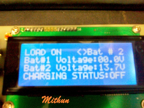
Advice for commuters: If you ride the e-bike to work, you may choose to install the solar charging facility at your place of work to allow daytime charging, but you will lose the lights at home. If you install the solar farm at home, you will need a second bike battery to allow one to be on charge and the other on the bike. (Or just get another whole e-bike like me J and swop them every day. With 2 bikes you can always invite a friend to join you on weekend rides. J
J)
Cost? Here is my solar farm’s investment broken down:
150 W solar modules                 R2 250, do not pay more than R15 per watt
12 V deep cycle LA battery        R1 500 – R2 000 for 150 Ah
10 A Charge regulator                R450 – R1 800 depending on model
600 watt inverter                        R2 100 –is depending on model.
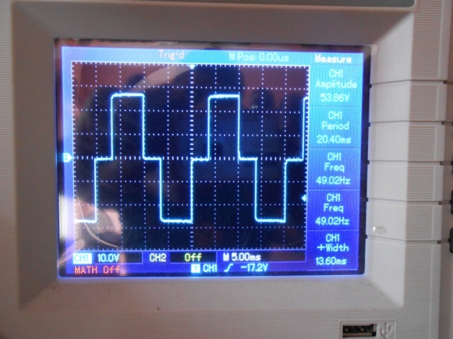
My experience is that the Lion charger does not like being driven from a ‘modified sine wave’ inverter, it simply shuts down. So you have to invest more and get a pure sine wave inverter. The spin-off is that it can also drive your TV and other light loads like i-goeters, should the ‘Power Giant’ let you down one stormy night. Of course, you can get a Lion bike charger that runs directly off 12 VDC and you do not need the inverter at all.
Total R6 300. 150 watt harvested over 6 hours 40 minutes per day comes to 1 kWh, which currently costs about R1,30 a unit. So you can now see that even if you flatten your bike’s 400 Wh battery twice every day and recharge successfully twice every day, given some 25 % inefficiency in the chain, it will take 4 846 days (= 13 years and 3 months) to break even, IF the LA batteries last more or less for ever and not only 3 – 4 years…
So why do it? Because it can/SHOULD be done! And because my house cannot go dark any more.


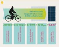
10 Reasons to use an electric bicycle:


1. Space-efficient to park
Electric bikes need just as little parking space as any bike, but because of their ease of use they have the potential to convince 30 % of car drivers to move to cycling.
This creates space for more greenery and play areas in town centres.


2. More mobility in less space

Electric bikes offer much mobility but take little road space, be- cause they allow people to keep up an even and matching pace largely irrespective of gradients or headwinds. They use the available road space more efficiently while still allowing riders to cover similar distances to typical car journeys in town and in rural local transport.


3. Comfortable, cheap and and definitely faster than a car around town

Compared to public transport or cars, electric bikes are in general considerably more affordable. Costs for an electric bike currently stand at around R400 per month (based on 4 year battery life and bike value of R20 000 and spares and maintenance costs of R1500 per year) or less, including depreciation of purchase cost, maintenance and wear.


4. Emissions saving
Electric bikes cause only minor CO2 emissions, are silent and emit zero particulate matter.


5. Safe

Electric bikes are safer in traffic because they are slower and lighter than cars. Statistics show that the probability of early death due to lack of exercise is considerably higher than when you ride your bike to work every day and tackle the traffic without being in a ‘sheet metal tank’.


6. Mobility enhancing

Electric bikes are at least as good as cars for satisfying most everyday mobility requirements, just cheaper, cleaner and healthier.


7. Health enhancing

According to the WHO (World Health Organization), 30 minutes of cycling every day can extend life by 8 healthy years. This applies equally and more for electric bikes, because they can easily and beneficially be used by unfit people or people with health problems to get back into cycling. Furthermore, with suitable electric bikes you can find even more opportunities with which to combine exercise where previously a car was needed, for example transporting cargo or children.


8. Energy efficient

With 250 Wh you can travel 33 km, while the same amount of energy can hear just 10 litres of water from tap temperature to shower temperature. According to Wikipedia a shower takes around 60 litres of water, so in energy terms it’s equivalent to 198 km of electric bike riding.


9. Sustainable

CO2 emissions can be reduced even further with the use of electricity from renewable sources.
0.3 m2 of solar panels installed on a central European house roof (for SA this will be even better!!) provides sufficient electricity with which to ride a electric cycle 5000 km.


10. Climate targets

The more people ride electric bikes the easier it will be to achieve CO2 reduction targets, especially because electric bikes increasingly replace car journeys. However also very significant for the CO2 footprint of an electric bike is what you feed yourself ! The electric bike is a hybrid vehicle combining electric motor and internal combustion engine (and in this case the rider is the IC engine, converting biomass – our food – internally into the form of work moving the pedals). Given this, just as with electrical energy, it is only via decentralised production and decentralised consumption of this food that the 
highest overall efficiency can be achieved.
FOR MORE Details CLICK HERE

Electro-kinetic road ramp for power generation & Switch Mode Inverter

Switch Mode Inverter

A switch mode inverter is such kind of inverter that use a switching regulator to convert the DC voltage to another DC voltage and then convert this DC to AC voltage. As the high frequency switching voltage converter is more efficient than the regular converters so switch mode inverter is more efficient than the normal low frequency inverter. But the circuit is more complex than the normal low frequency inverters. Unlike a linear power supply, the pass transistor of a switching-mode supply continually switches between low-dissipation, full-on and full-off states, and spends very little time in the high dissipation transitions, which minimizes wasted energy. Ideally, a switched-mode power supply dissipates no power. Voltage regulation is achieved by varying the ratio of on-to-off time. In contrast, a linear power supply regulates the output voltage by continually dissipating power in the pass transistor. This higher power conversion efficiency is an important advantage of a switched-mode power supply. Switched-mode power supplies may also be substantially smaller and lighter than a linear supply due to the smaller transformer size and weight. Switching regulators are used as replacements for linear regulators when higher efficiency, smaller size or lighter weight are required.
So what is the steps to make a switch mode inverter?
Yes! First of all, we need to find the block diagram of a switch mode inverter.
we have a input here, and we need to convert this input low voltage to a high voltage. Because we need to get 220V AC in the last. So what we need? we need 220X√2 = 311V DC to get 220V AC (ideally). So here is our first block diagram:
Image
Now we have a high voltage DC (315V). We have to keep this voltage little bit higher because, there will be some voltage loss in conversion. To get excellent result we have to make this voltage converter strong and clean in operation.
Then we have to convert this High Voltage DC into High Voltage AC(220V AC). To convert this DC to AC we need H-Bridge. So the next block diagram will be:
Image
And now we are getting out AC voltage. Yes! But its all theoretical. In real hardware its much more complex.
Now Lets see what I did in my case…
In my case I started from making a good DC to DC converter first. I started from very beginning, I made a flyback DC/DC converter first! But it was not good enough. Then I tried to make another one based on Push-Pull topology. And this time I got good result. And I was able to make this:
Image
The output was DC (>350V). And after some critical tests I was able to make another one. Besides, I made a H-Bridge to convert the DC into AC at the same time. The H-Bridge was working good. I used a micro-Controller (PIC16F73) to generate the pulses to drive the H-Bridge. Then I tested the H-Bridge with a low voltage (12VDC) to ensure that the Bridge is working pretty well. After ensuring, I made another DC/DC converter to take a load of 200W. And here is these two blocks:
Image
Yes! Its working.
Now its time to make something commercial. And I made this:
Image
And the Output wave-shape was:
Image
This was a first step to make a commercial design. Its capacity was 150W. And the last one was:                                                                                                       Image
This one was able to handle up to 400W load. The output was 50Hz 220V AC. I kept an option in this circuit that it can be used as normal inverter with changeover and with an option to add a charging adapter.


Electro-kinetic road ramp for power generation, the new way of thinking…

The electro-kinetic road ramp is a method of generating electricity by harnessing the kinetic energy of automobiles that drive over the ramp. In June 2009, one of the devices was installed in the car park at a Sainsbury’s supermarket in Gloucester, United Kingdom, where it provides enough electricity to run all of the store’s cash registers. The ramp was invented by Peter Hughes, an electrical and mechanical engineer who is employed by Highway Energy Systems Ltd. The company says that under normal traffic conditions, the apparatus will produce 30 kW of electricity. Other proposed applications for the road ramps include powering street and traffic lights, heating roads in the winter to prevent ice from forming, and ventilating tunnels to reduce pollution.
The idea was dismissed as Talk of ‘kinetic energy plates’ is a total waste of energy in the Guardian by David MacKay, the professor of natural philosophy in the department of Physics at the University of Cambridge. MacKay wrote, “The savings from parking at the green car park thus amount to one four-thousandth of the energy used by the trip to the supermarket.”
It is taken from wikipedia. Its really a awesome idea to generate power. Input is almost free! So, we can call it generating electricity for free! Yes, its one kind of free energy generation. In my own lab, I’m trying to make one of this ramp. It was a project work from a university student team, but I was trying to help them to make this awesome project.
First of all we need to know about the concept of the project. If we want to use the kinetic energy to convert it into electrical energy, we have to make a mechanical mechanism to rotate a generator. And the kinetic energy will come from the vehicles of the road.
First of all, we need to see this video to clear the concept.
Now its clear to us. So, we need to make the mechanical part first. I tried in my workshop with help of some experts in mechanical engineering as I’m not expert in that field. I’m expert  in electronics. Any way, one of my known person helped me to make the frame. For demonstration type mechanism, we made this:
05092013640
05092013641
The frame was made to handle up to 200Kg Load. Then we updated the frame and inserted the ramps. and the mechanism which will support the ramps. We used springs with shaft holder below the ramps so that the spring and shaft can’t displace. The system have come in this form:
14092013650
14092013652
14092013651
03102013674
03102013675
03102013676
03102013677
In the mean time, I designed the control circuit in my lab. In the control unit, I used two different batteries so that one can be used in case of the fail time of another one. Also, if one battery is fully charged then the system is able to charge the other one. And in case of load handling, the system will draw power from the first one until it discharged in the rated point. And then the system will switch the load to the second battery. This battery system can be extended in future if required. Also I put a sensor (LDR) so that the load( may be street lamp) can be used only at night time. This is totally optional. The control unit is here:                                                                01092013639
01092013638
08092013649
The total system is still under R&D. The mechanism is being tested. After fully tested, I’ll post the rest images and news about it. The final one will be something like this:
Ramp
The system is now fully ready and its working!!!
here is some field test images…
DSC00471
DSC00472
DSC00473
We hope, this system will be so popular soon…

For More details CLICK HERE

Working With PT100 & IR remote controlled auto/manual room temperature based Fan speed controller

Working With PT100:

Platinum resistance thermometers (PRTs) offer excellent accuracy over a wide temperature range (from -200 to +850 °C). Standard Sensors are are available from many manufacturers with various accuracy specifications and numerous packaging options to suit most applications. Unlike thermocouples, it is not necessary to use special cables to connect to the sensor.
The principle of operation is to measure the resistance of a platinum element. The most common type (PT100) has a resistance of 100 ohms at 0 °C and 138.4 ohms at 100 °C. There are also PT1000 sensors that have a resistance of 1000 ohms at 0 °C.
The relationship between temperature and resistance is approximately linear over a small temperature range: for example, if you assume that it is linear over the 0 to 100 °C range, the error at 50 °C is 0.4 °C. For precision measurement, it is necessary to linearise the resistance to give an accurate temperature. The most recent definition of the relationship between resistance and temperature is International Temperature Standard 90 (ITS-90).
pt100 sensorImage
This linearisation is done automatically, in software, when using Pico signal conditioners. The linearisation equation is:
Rt = R0 * (1 + A* t + B*t2 + C*(t-100)* t3)
Where:
Rt is the resistance at temperature t, R0 is the resistance at 0 °C, and
A= 3.9083 E-3
B = -5.775 E-7
C = -4.183 E -12 (below 0 °C), or
C = 0 (above 0 °C)
For a PT100 sensor, a 1 °C temperature change will cause a 0.384 ohm change in resistance, so even a small error in measurement of the resistance (for example, the resistance of the wires leading to the sensor) can cause a large error in the measurement of the temperature. For precision work, sensors have four wires- two to carry the sense current, and two to measure the voltage across the sensor element. It is also possible to obtain three-wire sensors, although these operate on the (not necessarily valid) assumption that the resistance of each of the three wires is the same.
The current through the sensor will cause some heating: for example, a sense current of 1 mA through a 100 ohm resistor will generate 100 µW of heat. If the sensor element is unable to dissipate this heat, it will report an artificially high temperature. This effect can be reduced by either using a large sensor element, or by making sure that it is in good thermal contact with its environment.
Using a 1 mA sense current will give a signal of only 100 mV. Because the change in resistance for a degree celsius is very small, even a small error in the measurement of the voltage across the sensor will produce a large error in the temperature measurement. For example, a 100 µV voltage measurement error will give a 0.4 °C error in the temperature reading. Similarly, a 1 µA error in the sense current will give 0.4 °C temperature error.
Because of the low signal levels, it is important to keep any cables away from electric cables, motors, switchgear and other devices that may emit electrical noise. Using screened cable, with the screen grounded at one end, may help to reduce interference. When using long cables, it is necessary to check that the measuring equipment is capable of handling the resistance of the cables. Most equipment can cope with up to 100 ohms per core.
The type of probe and cable should be chosen carefully to suit the application. The main issues are the temperature range and exposure to fluids (corrosive or conductive) or metals. Clearly, normal solder junctions on cables should not be used at temperatures above about 170 °C.
Sensor manufacturers offer a wide range of sensors that comply with BS1904 class B (DIN 43760): these sensors offer an accuracy of ±0.3 °C at 0 °C. For increased accuracy, BS1904 class A (±0.15 °C) or tenth–DIN sensors (±0.03 °C). Companies like Isotech can provide standards with 0.001 °C accuracy. Please note that these accuracy specifications relate to the SENSOR ONLY: it is necessary to add on any error in the measuring system as well.
Now come to the point. When you really need to use PT100, then you may think that you will use something like this:
PT100
And you will measure the voltage with the MCU. But if you really planning this, you’ll be disappointed. Because in this case you may need MCU with 32bit ADC. And such MCU is not available in most of the local market(it was not at available in my local market). Also there will be a very little change in the voltage with the temperature changes. So it will be definitely critical to measure the temperature in this method.
So what to do now?
You’ve many ways open still now. You can use Bridges(such as Wheatstone Bridge) or you can use Op-Amp to do this job for you. Basically Wheatstone Bridge will be a complex one to do the job but will ensure good performance. But if you don’t need to much accuracy and you don’t want to be such complex, you can use Op-Amp.
What I did in my case? In my case, I didn’t need so much accuracy. So I used Op-Amp. And did a back calculation. 
Ha ha ha! I made a amplifier with a gain of 4.7. And then set the sensor in a known standard heater. Now the time of back calculation.
I set the heater at
50′C—-> measured the output voltage at the Op-Amp output terminal.
55′C—-> measured the output voltage at the Op-Amp output terminal.
60′C—-> measured the output voltage at the Op-Amp output terminal.
.
.
.
.
200′C—-> measured the output voltage at the Op-Amp output terminal.
205′C—-> measured the output voltage at the Op-Amp output terminal.
And so on…
now, took the data in a table. Now you can imagine what I’m planning to do…
Yes! I coded a look-up table. and from that, I found the temperature data with 5′C steps.
  Its done! without any complexity. But if you really need higher accuracy, You must have to use the Bridges.


IR remote controlled auto/manual room temperature based Fan speed controller.

The main job of this project was to control a fan speed depending on the room temperature in Auto mode and as user defined in Manual Mode.
auto Fan
In the Auto mode, the micro-controller (PIC16F73) take the data from the temperature sensor LM35. The LM35 is a precession temperature sensor that have a output of 10mV/’C. So what I did actually here, I kept the ADC_ref. Voltage at 2.5V. So it will count 2.5/255 = 9.8mV/Cnt. Which is almost same as the LM35 provides per ‘C. In Auto mode the fan speed will vary with the temperature changes. When temperature rises, fan speed increases. Temperature falls, speed reduces.
But in Manual mode, user have a choice of His/Her own. A remote (SONY) is provided, the Power button will select the Mode (Auto/Manual) and if Manual Mode is selected, button 1 to 9 will change the fan speed and 0 will stop the fan. A Buzzer is used to inform the user that a button has pressed.
Here is the complete circuit:
30072013618

For More Details CLICK HERE

Popular Posts