


MPPT Solar Charge Controller:
First of all, What is MPPT?
MPPT stands for Maximum Power Point Tracker.
A MPPT, or maximum power point tracker is an electronic DC to DC
converter that optimizes the match between the solar array (PV panels),
and the battery bank or utility grid. To put it simply, they convert a
higher voltage DC output from solar panels (and a few wind generators)
down to the lower voltage needed to charge batteries.
So How the Optimization works?
Most PV panels are built to put out a nominal 12 volts. The catch is
“nominal”. In actual fact, almost all “12 volt” solar panels are
designed to put out from 16 to 22.5 volts. The problem is that a nominal
12 volt battery
is pretty close to an actual 12 volts – 10.5 to 12.7 volts (depending
on state of charge). Under charge, most batteries want from around 13.2
to 14.4 volts to fully charge – quite a bit different than what most
panels are designed to put out.Lets take a 120W Solar Panel. The panel in this range will have a Imp & Vmp (Imp= Maximum Current, Vmp = Maximum Voltage). And the product of these two parameter will produce that 120W. In this 120, Imp = 6.85A & Vmp = 17.5 so the Maximum power is 6.85X17.5 = 120W.
Now lets see what happen in reality. The battery voltage is not fixed,we see in past. So when a battery is under charge, the voltage rises up. That means the voltage difference between the battery and panel decreases. That cause current reduction according to Ohms Law. So what is happening here? Your Panel is providing 6.85A (say). And the battery voltage is 12.0 (initially). So what the charging power? 12X6.85 = 82W. That means you are having a power loss of 120-82 = 38W!!! But you paid for this too.
So, what happen if we optimize the charging method a little bit? Lets have a DC to DC converter that always works at the Imp & Vmp of the panel have and convert this power into another voltage that feed the battery. Now lets see what is happening.
The DC to DC converter is taking 6.85A & 17.5V so the power is 120W. And the battery voltage is 12.0V (say), so the current at the battery terminal will be 120W/12.0V = 10A !!! Nice!!!.
So This is how the optimization works. So that you get the maximum power from the panel you have.
So how the MPPT Charge Controller Works?
A MPPT Charge controller is nothing but a high efficient DC to DC converter that can work in various point of voltage and current. The converter is controlled by a micro-controller that calculate the maximum points of the panel and set the converter duty cycle. So that the converter gets the maximum power from the panel.
MPPT’s are most effective under these conditions:
Winter, and/or cloudy or hazy days – when the extra power is needed the most.
- Cold weather – solar panels work better at cold temperatures, but without a MPPT you are losing most of that. Cold weather is most likely in winter – the time when sun hours are low and you need the power to recharge batteries the most.
- Low battery charge – the lower the state of charge in your battery, the more current a MPPT puts into them – another time when the extra power is needed the most. You can have both of these conditions at the same time.
- Long wire runs – If you are charging a 12 volt battery, and your panels are 100 feet away, the voltage drop and power loss can be considerable unless you use very large wire. That can be very expensive. But if you have four 12 volt panels wired in series for 48 volts, the power loss is much less, and the controller will convert that high voltage to 12 volts at the battery. That also means that if you have a high voltage panel setup feeding the controller, you can use much smaller wire.
Here is what I did in my Lab. First of all, I made a DC to DC converter. Tested it with varying the duty cycle. And it works.
And then I do research with the panel. And I tried to find the maximum points of the panel. After a long time research, I found it. There is many algorithms to find the MPP of a solar panel. First of all I just coded based on panel voltage. That works but not so efficient. And doing more research I was able to establish the complex one that works good in all condition.
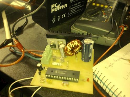
Finally I made one for 12V 40A rating. And here is that one!

Looking good. Yes! Its working Good.
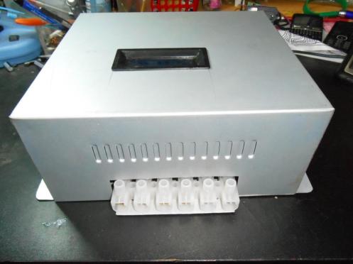
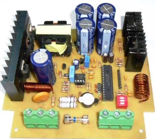
And a small one for 12V10A range is here:
System Modification of Thermal Bath:
It was a old laboratory instrument. The main circuit was very old. As the instrument work with acids so the circuit was damaged due to corrosion.Here is the inside view before operation:
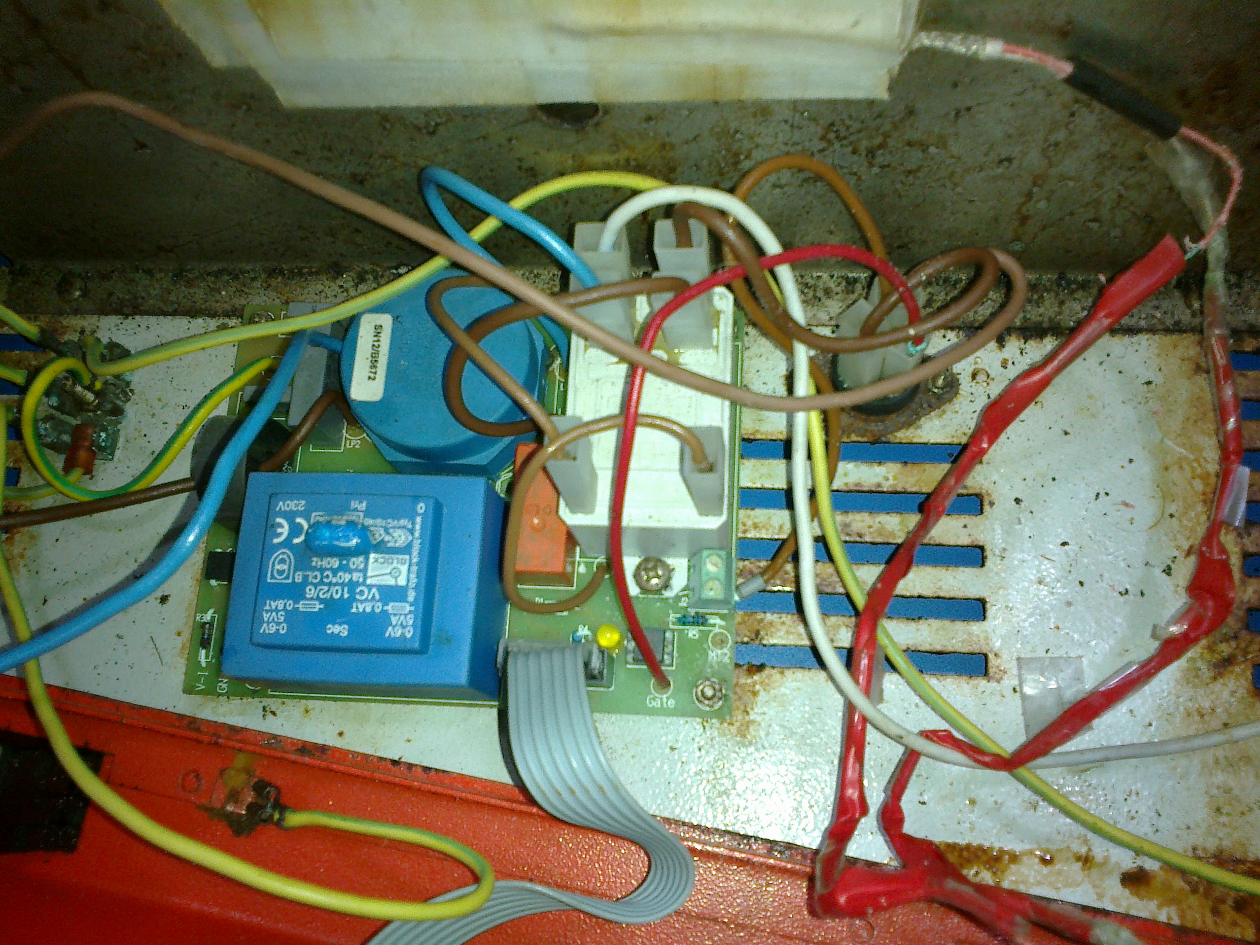
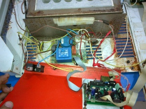
These is are the inside view of the Heater controller. The main function of this heater controller was to control the heat as user put the value and a timer. When the time was given and a start button is pressed, the controller started. And when the time ends, the controller stops. The temperature is kept fixed as the user selected.
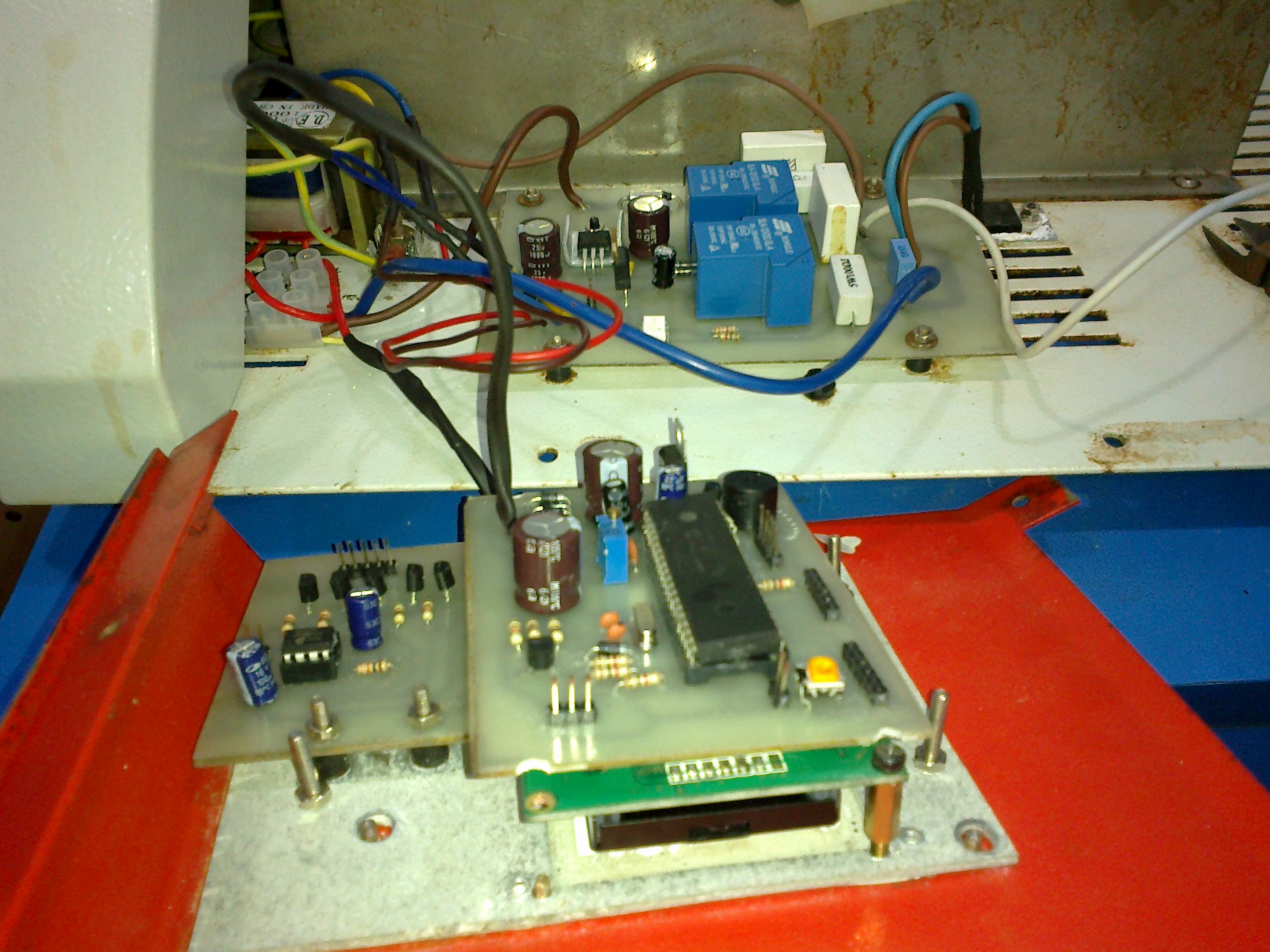
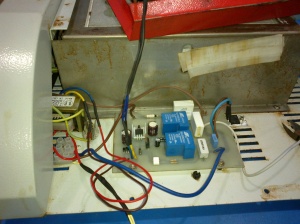
Both of the control card and the Display card was damaged due to chemical corrosion. So I need to changed these two circuits. But as these machines are not available now in the local market, so I modified the circuit with devices what is available in our local market. Here is the circuit what is done in M’s Lab:
And the front panel. Here I had no chance to change the front panel rather than change the control system. What I actually did here is I fixed a remote controlled switch that is fitted behind the front panel.
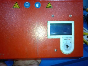
This remote is based on SIRC protocol. I used SONY TV remote as its cheap and available in local market.
And finally I fit all the circuits and fitted the cover. And tested it. Its done! Its working!
For more details CLICK HERE

No comments:
Post a Comment
Note: only a member of this blog may post a comment.