


GSM Based vehicle security system Final Year Project
Its a very simple but interesting project. For vehicle tracking system also know as VTS we use a module that have both GPS and GSM such as SIM900. But in this project, we can do a simple but interesting vehicle security system.Working mechanism:
First of all, there is a vibration sensor placed in the vehicle. When vehicle moves, its vibrates. So, the sensor generates a signal. The signal is then sensed by the micro-controller(PIC18F4550). And the micro-controller do the rest.
There is a GSM module, MOD9001 used in this project[any other module also can be used with GPS too]. When the system is standby, the micro-controller keep sending some commands to the module to keep it synchronized. And when the vibration sensor generates a signal to MCU, it sends some set of commands to the MOD9001 so that it sends a sms to a prefixed cell phone. Micro-controller is connected with the GSM module via RS-232 cable and there is a MAX-232 in between modem and micro-controller.
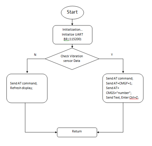
Here is the algorithm of the project:
Here you can see the module datasheet [MOD9001].
To send a SMS vis GSM module, its need to send some commands in sequence; Fist of all, MCU sends ‘AT’ command via RS-232. Then, modem replies with sending back ‘OK’. Then MCU sends: ‘AT+CMGF=1′; this set the modem to text mode. After receiving a ‘OK’ from modem, MCU then sends ‘AT+CMGS=”mobile number”. Modem replies with ‘>’ then MCU sends the message and sends a command in ASCII, ‘Ctrl+Z’. This set the modem to send the sms to the given mobile number.
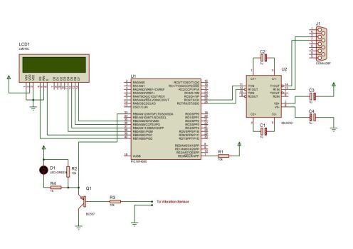
Here is the circuit diagram of the project:
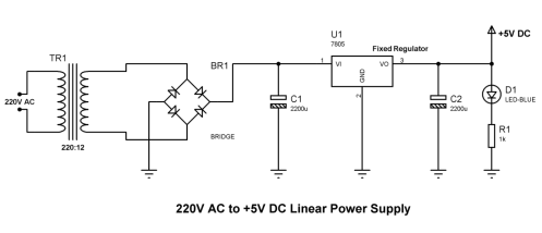
The DC power supply of the above system is here:
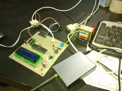
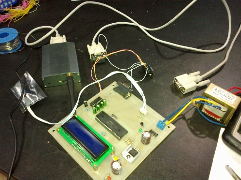
And here is some pictures when the project was under R&D:
Simple Two Transistor Buck Converter:
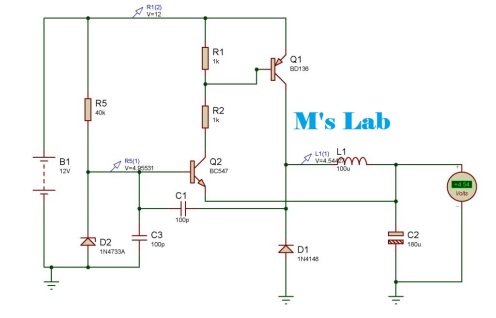
This time I’ll show you how to make a simple two transistor buck converter. Buck converter is a switch mode converter that converts high voltage into low voltage. This type of converter frequently required in electronic circuits. As this type of converter is more efficient that the regular linear circuits so it is recommended in most of the circuits. Also this type of circuit have a good regulation.Here is the circuit:
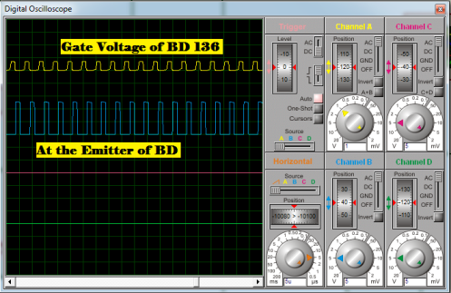
And the waveform of the circuit in different points:
The output voltage can be controlled by the Zener Diode used here. The output voltage I’ve got experimentally is around Vzd-0.5; where Vzd = Zener Voltage.
This type of converter have many benefits:
* Only 2 ordinary transistors are used. * Just few extra parts required with that two transistors. * Low Cost with good efficiency. * Can be used as a ordinary LM78XX regulators. * No noise for the inductive section. I’ve build one for me and tested it. Hope you will make your own and the circuit will help you.
For More Details CLICK HERE :


No comments:
Post a Comment
Note: only a member of this blog may post a comment.