


7-Segment Voltmeter:
First of all, we need to know how a
multiplexed 7-segment display works. When 4 segments are connected as
one segment then the data bus of all the segments are in parallel but
the enable pin is different for all segments. Thus we have a chance to
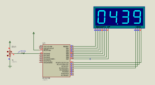
control the segments. Let’s see the image below:
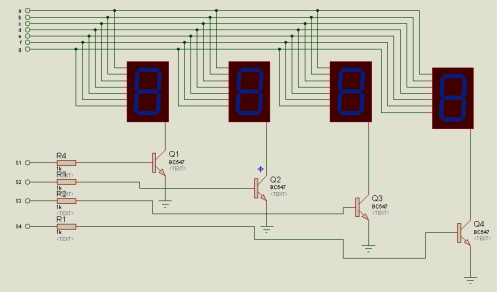
Here the data is send thorough the ‘a, b,
c, d, e, f, g’ line and the ‘s1, s2, s3, s4’ are the enable line. When a
data is send via the data bus and the s1 is high, what will happen? The
data will be shown in the first segment. Yes. Similarly when s2 is
high, the data will be shown in the second segment. This is how the
multiplexed seven segment works. But now the question is how can we show
different data in these 4 segments at a time? Remember, out eyes can’t
find the difference within 10ms. That’s the point. If we can change the
data with corresponding enable pins of all these 4 segments within 10ms,
our eyes will see a set of 4 digits in this segment.
Let’s do the program:
In the program what we have to really?
First we need timing so that we can send different data in different
time with keeping high the corresponding enable pin of the segment. So
we need an timer interrupt.
Here we are doing a timer interrupt. And the timer interrupt setting is:
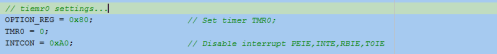
These are all for timer interrupt. Now
our timer is ready. But what next? We have to do the other program.
First of all, the port initialization:
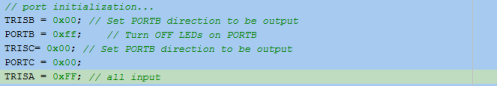
Then, we need the other initial values:

And for Analog/Digital conversion:
In the while(1) section, we need the other works to do.
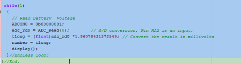
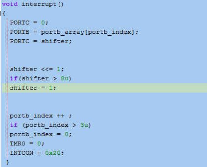
What is happening here? In the first
line, we are initializing the ADC channel0 to take the signal. Then, the
signal is taken. But in the 3rd line, tlong =
(float)adc_rd0*19.607843… ; from where it comes from? Do this:
(5/255)X100. 5= VDD, 255 for 8bit and 100 to reduce fractional
error(we’ll see it later).
Now, what is ‘number’ here? To know what is this ‘number’ for we need to see what the display() sub program does.
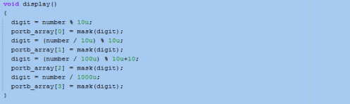
Here, the number is used to extract the data. But, another term comes in, ‘mask’. What is this mask?
Then see this:
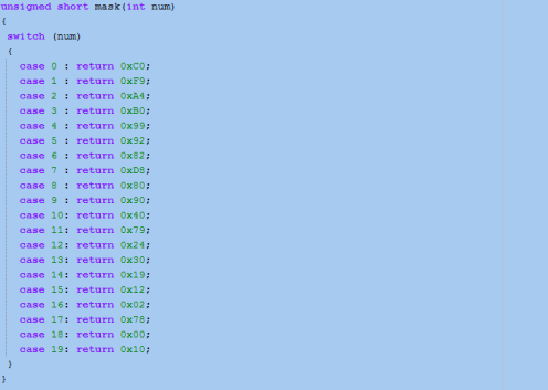
Actually we are converting the data for
the 7-segment display in the ‘mask’. Now the microcontroller is taking
the analog signal through the AN0 pin of PIC16F73, and then taking the
corresponding digital data. And then, the data is being calculated and
extracted for each segment. And then the micro-controller is sending
this 4 different data to the 4 different segments making enable the
right segment within 10ms. So our eyes see just a 4 digits number. So
here is our full project:
Digital AC Lamp intensity controller
First of all How a AC Lamp Dimmer works?The AC Lamp Dimmer is nothing but a voltage regulator for the AC load. But we can easily regulate DC voltage to the load terminal. But how can we regulate the AC voltage? With POT(Variable Resistor)? No. To control the AC power, we need to use Thyristors.
What is Thyristor?
A thyristor is a solid-state semiconductor device with four layers of alternating N and P-type material. They act as bistable switches, conducting when their gate receives a current trigger, and continue to conduct while they are forward biased (that is, while the voltage across the device is not reversed).
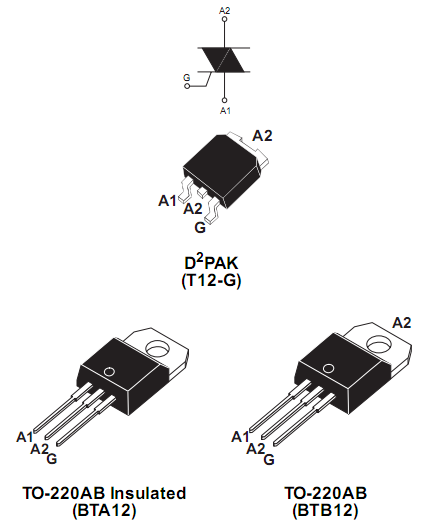
There is a lots of details information about Thyristor over internet. So better you google for it. Here in our project we will use BTA12:
Now what we really need to do?
We just want to control the output phase angle of the sine wave AC signal. So that we can control the lamp brightness easily. Here is a simple animated wave shape so that you can understand it easily:
Now how to do this with Micro-Controller?
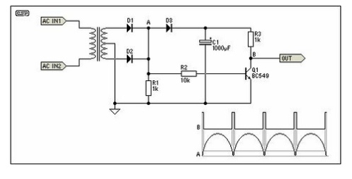
In this case, we need to know what to do with MCU. Actually we need to sense the zero-crossing signal first. You can find many circuits but here is the simplest one:
So we know the zero-crossing points. Taking it as a interrupt we can easily design a micro-controller based system which can generate a gate firing signal. And this signal will trigger the gate of the TRIAC. But a problem occurs again. The micro-controller works at 5V DC on the other hand the TRIAC works at 220V AC. So how can I trigger the TRIAC with MCU? So we need a coupler, Opto-isolator. I’m not writing about opto-isolator here, better you go google for it.
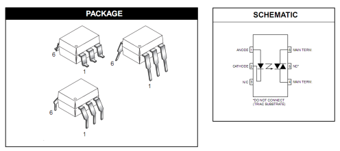
Anyway, we’ll use MOC3021 Opto-Isolator here in this project. Here is this:
Now lets make a project with micro-controller. Here I’ll demonstrate with PIC12F675. Compiler: MicroCpro for PIC. But first, lets make a schematic on Proteus ISIS. Here is the diagram:
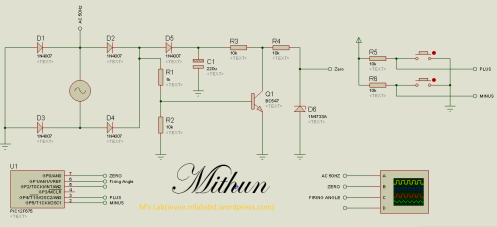
NOTE:MITHUN is my petname
And the TRIAC unit:
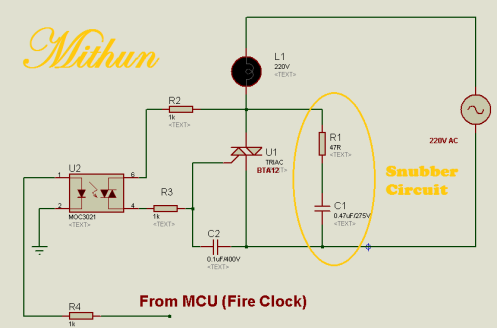
A new term comes, snubber. What is snubber? Click this link “Snubber” to read more about snubber ‘cz I’m not elaborating here.
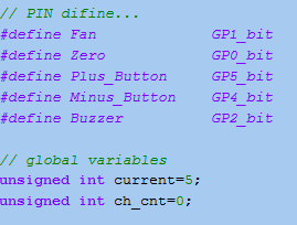
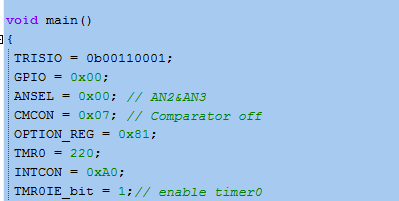
Our Diagram is now ready. So its time to do some programming. Lets start MicroCpro for PIC. But what we need here? I mean what is the algorithm? Very simple. Find the zero-crossing, and make a firing clock. But first we need to define the variables.
Now we need an interrupt so that we can check the zero-crossing signal. Here I’ll use just a timer interrupt mechanism to make the project simple.
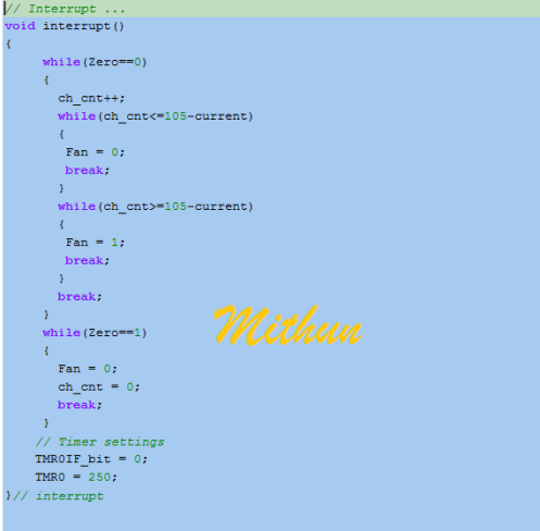
What is happening here, the counter is reset in each zero-crossing signal goes low to high.
Now Lets do the initialization:
Now the MCU is initialized. So we need to do rest of the program:
Its like this:
while(1)
{
while(!Minus_Button)
{
if(current<90)
{
current+=10;
Delay_ms(20);
}
else
{
current = 100;
}
Buzzer = 1;
Delay_ms(50);
Buzzer = 0;
break;
}
while(!Plus_Button)
{
if(current>11)
{
current-=10;
Delay_ms(20);
}
else
{
current = 0;
}
Buzzer = 1;
Delay_ms(50);
Buzzer = 0;
break;
}
}// While
So finally Our program is ready. And now we can check it with proteus ISIS. In my case, I got the wave shape like this:
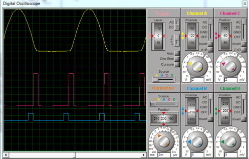
The wave in yellow color is presenting the AC sine wave in half cycle mode, but in real its working as the full cycle mode. And the pulse in red color is our that zero-crossing signal and we are generating the firing signal shown in blue color.
And the real hardware is here:
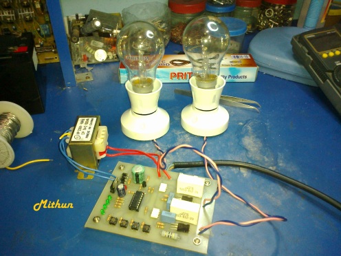
Ops!!! There is two Lamps here but we did for one in this project.
If you really understand the project, you can do it for not only for one but for as many as you want. So do not panic. Just try to understand the project, and make it for yourself.


No comments:
Post a Comment
Note: only a member of this blog may post a comment.