


Switch Mode Inverter
A switch mode
inverter is such kind of inverter that use a switching regulator to
convert the DC voltage to another DC voltage and then convert this DC to
AC voltage. As the high frequency switching voltage converter is more
efficient than the regular converters so switch mode inverter is more
efficient than the normal low frequency inverter. But the circuit is
more complex than the normal low frequency inverters. Unlike a linear power supply, the pass transistor of a switching-mode supply continually switches between low-dissipation,
full-on and full-off states, and spends very little time in the high
dissipation transitions, which minimizes wasted energy. Ideally, a
switched-mode power supply dissipates no power. Voltage regulation
is achieved by varying the ratio of on-to-off time. In contrast, a
linear power supply regulates the output voltage by continually
dissipating power in the pass transistor.
This higher power conversion efficiency is an important advantage of a
switched-mode power supply. Switched-mode power supplies may also be
substantially smaller and lighter than a linear supply due to the
smaller transformer size and weight. Switching regulators are used as
replacements for linear regulators when higher efficiency, smaller size
or lighter weight are required.
So what is the steps to make a switch mode inverter?
Yes! First of all, we need to find the block diagram of a switch mode inverter.
we have a input here, and we need to
convert this input low voltage to a high voltage. Because we need to get
220V AC in the last. So what we need? we need 220X√2 = 311V DC to get
220V AC (ideally). So here is our first block diagram:
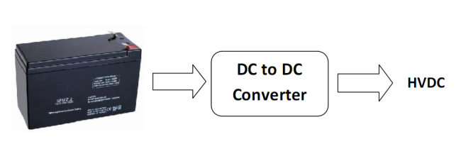
Now we have a high voltage DC (315V). We
have to keep this voltage little bit higher because, there will be some
voltage loss in conversion. To get excellent result we have to make this
voltage converter strong and clean in operation.
Then we have to convert this High Voltage DC into High Voltage AC(220V AC). To convert this DC to AC we need H-Bridge. So the next block diagram will be:
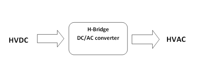
And now we are getting out AC voltage. Yes! But its all theoretical. In real hardware its much more complex.
Now Lets see what I did in my case…
In my case I started from making a good DC to DC converter first. I started from very beginning, I made a flyback DC/DC converter first! But it was not good enough. Then I tried to make another one based on Push-Pull topology. And this time I got good result. And I was able to make this:
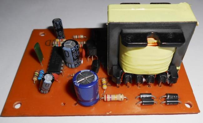
The output was DC (>350V). And after
some critical tests I was able to make another one. Besides, I made a
H-Bridge to convert the DC into AC at the same time. The H-Bridge was
working good. I used a micro-Controller (PIC16F73) to generate the
pulses to drive the H-Bridge. Then I tested the H-Bridge with a low
voltage (12VDC) to ensure that the Bridge is working pretty well. After
ensuring, I made another DC/DC converter to take a load of 200W. And
here is these two blocks:
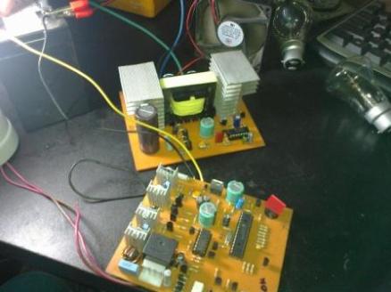
Yes! Its working.
Now its time to make something commercial. And I made this:
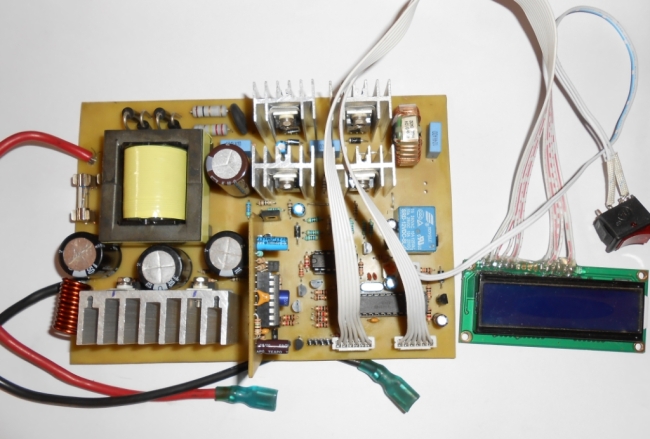
And the Output wave-shape was:
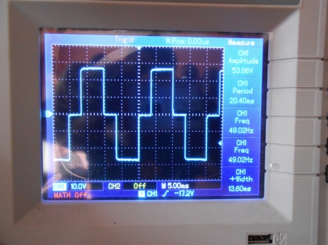
This was a first step to make a
commercial design. Its capacity was 150W. And the last one was:
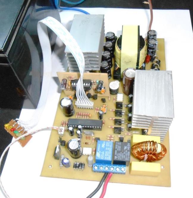
This one was able to handle up to 400W
load. The output was 50Hz 220V AC. I kept an option in this circuit that
it can be used as normal inverter with changeover and with an option to
add a charging adapter.
Electro-kinetic road ramp for power generation, the new way of thinking…
The electro-kinetic road ramp
is a method of generating electricity by harnessing the kinetic energy
of automobiles that drive over the ramp. In June 2009, one of the
devices was installed in the car park at a Sainsbury’s supermarket in Gloucester, United Kingdom,
where it provides enough electricity to run all of the store’s cash
registers. The ramp was invented by Peter Hughes, an electrical and
mechanical engineer who is employed by Highway Energy Systems Ltd. The
company says that under normal traffic conditions, the apparatus will
produce 30 kW of electricity. Other proposed applications for the road
ramps include powering street and traffic lights, heating roads in the
winter to prevent ice from forming, and ventilating tunnels to reduce
pollution.
The idea was dismissed as Talk of ‘kinetic energy plates’ is a total waste of energy in the Guardian by David MacKay, the professor of natural philosophy in the department of Physics at the University of Cambridge.
MacKay wrote, “The savings from parking at the green car park thus
amount to one four-thousandth of the energy used by the trip to the
supermarket.”
It is taken from wikipedia. Its really a
awesome idea to generate power. Input is almost free! So, we can call it
generating electricity for free! Yes, its one kind of free energy
generation. In my own lab, I’m trying to make one of this ramp. It was a
project work from a university student team, but I was trying to help
them to make this awesome project.
First of all we need to know about the
concept of the project. If we want to use the kinetic energy to convert
it into electrical energy, we have to make a mechanical mechanism to
rotate a generator. And the kinetic energy will come from the vehicles
of the road.
First of all, we need to see this video to clear the concept.
Now its clear to us. So, we need to make
the mechanical part first. I tried in my workshop with help of some
experts in mechanical engineering as I’m not expert in that field. I’m
expert in electronics. Any way, one of my known person helped me to
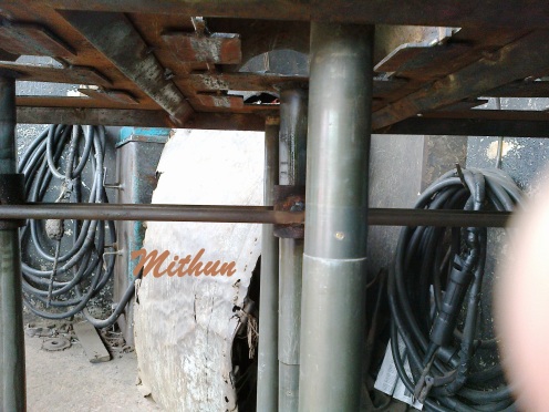
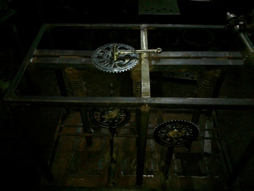
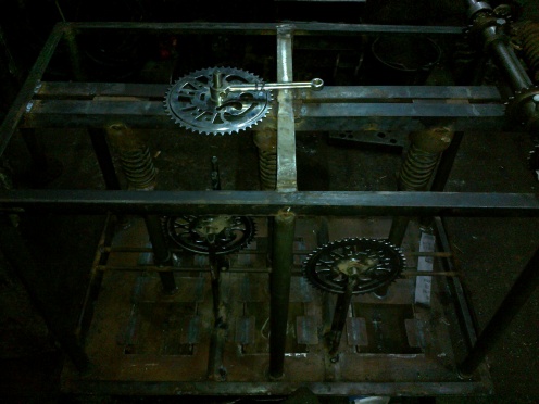
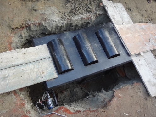
make the frame. For demonstration type mechanism, we made this:
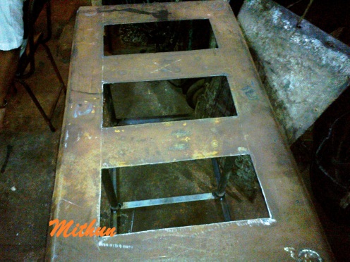

The frame was made to handle up to 200Kg
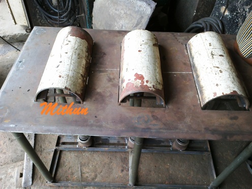
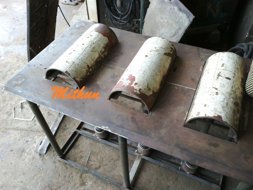
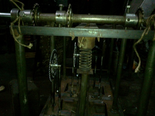
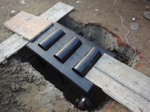
Load. Then we updated the frame and inserted the ramps. and the
mechanism which will support the ramps. We used springs with shaft
holder below the ramps so that the spring and shaft can’t displace. The
system have come in this form:
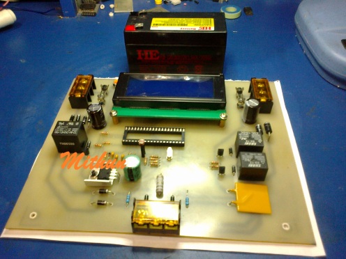
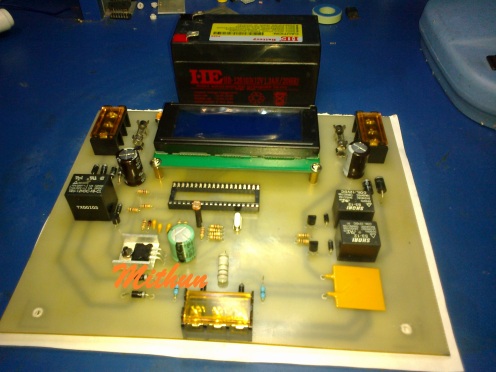
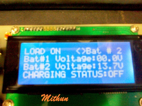
In the mean time, I designed the control
circuit in my lab. In the control unit, I used two different batteries
so that one can be used in case of the fail time of another one. Also,
if one battery is fully charged then the system is able to charge the
other one. And in case of load handling, the system will draw power from
the first one until it discharged in the rated point. And then the
system will switch the load to the second battery. This battery system
can be extended in future if required. Also I put a sensor (LDR) so that
the load( may be street lamp) can be used only at night time. This is
totally optional. The control unit is here:
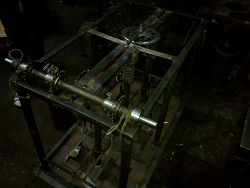
The total system is still under R&D.
The mechanism is being tested. After fully tested, I’ll post the rest
images and news about it. The final one will be something like this:
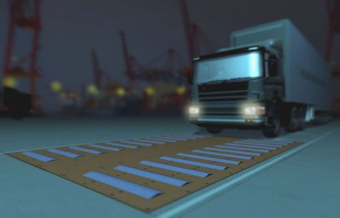
The system is now fully ready and its working!!!
here is some field test images…

We hope, this system will be so popular soon…
For More details CLICK HERE

No comments:
Post a Comment
Note: only a member of this blog may post a comment.